🔍 Comparators and Signal Conditioning
So far, we’ve learned how to amplify signals. Now we move to the next critical step in real-world electronics:
👉 deciding (yes/no) and preparing signals so digital systems can understand them.
This is where comparators and signal conditioning come in.
⚖️ Comparators – The Yes/No Decision Maker
A comparator answers a simple question:
“Is this voltage higher than that voltage?”
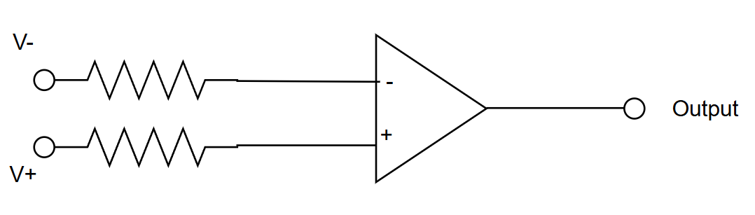
How a Comparator Works
- Voltage at non-inverting (+) input
- Voltage at inverting (−) input
Behavior:
- If → Output goes HIGH
- If → Output goes LOW
There is no feedback.
The op-amp is used in open-loop mode, so even tiny differences force the output to saturate.
🧪 Practical Comparator Example
Temperature sensor:
Threshold:
Comparator Setup
- Sensor →
- Reference →
Result:
- Temperature < → Output LOW
- Temperature > → Output HIGH (alarm ON)
Simple. Effective.
⚠️ Comparator Problem: Noise & Chatter
Near the threshold:
- Noise
- Ripple
- Sensor instability
This causes the output to rapidly toggle: HIGH → LOW → HIGH → LOW
This is chattering, and it’s bad for:
- Relays
- Digital inputs
- Microcontrollers
🔁 Hysteresis – The Stability Fix
Hysteresis adds two thresholds:
- One for turning ON
- One for turning OFF

In the graph is lower threshold and is upper threshold
Hysteresis is introduced using positive feedback, creating two different switching thresholds:
-
Upper Threshold ()
-
Lower Threshold ()
This prevents noise from causing multiple output transitions near the threshold.
Just like a thermostat.
Example
- Turns ON at
- Turns OFF at
Noise between no longer matters.
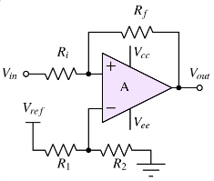
Inverting Comparator with Hysteresis
The input signal is applied to the inverting terminal. The reference and feedback network sets the hysteresis window.
Threshold Voltages
Hysteresis Width
Resistor Ratio
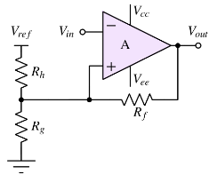
Non-Inverting Comparator with Hysteresis
The input signal is applied to the non-inverting terminal. Positive feedback shifts the reference voltage dynamically.
Threshold Voltages
Hysteresis Width
Resistor Ratio
Design Guidelines
- and are the comparator output high and low saturation voltages
- Choose resistor values between 10 kΩ and 1 MΩ
- Higher resistance reduces power consumption but increases noise sensitivity
How Hysteresis Is Added
By feeding a small portion of the output back to the input (positive feedback).
Result:
- Clean transitions
- Stable digital output
- Perfect for MCU inputs
📌 A comparator without hysteresis is incomplete in real systems.
🌉 Signal Conditioning – Bridging Analog and Digital
Microcontrollers don’t understand raw sensor signals well.
Signal conditioning prepares signals so the ADC or digital input can read them correctly.
🛠️ Problems Signal Conditioning Solves
1️⃣ Tiny Signals
Sensor:
ADC wants:
✅ Solution: Amplification
2️⃣ Noisy Signals
Long wires, EMI, motors, switching supplies introduce noise.
✅ Solution: Filtering
3️⃣ Offset Signals
Sensor:
ADC wants:
✅ Solution: Offset removal + gain
4️⃣ Loading Problems
Sensor has high output impedance → voltage droops.
✅ Solution: Buffering
🧱 Signal Conditioning Building Blocks
Typical stages:
- Amplification
- Filtering
- Level Shifting
- Buffering
📊 Simple Conditioning Example
Pressure sensor:
Arduino ADC:
Required gain:
Result:
- bar maps cleanly to counts
- Excellent resolution
- Low noise
🎛️ Filtering – Removing Noise
RC Low-Pass Filter
- Passes slow sensor changes
- Blocks fast noise
Cutoff frequency:
Active Filters (Op-Amp Based)
- No loading
- Precise cutoff
- Gain + filtering together
Preferred for sensor interfaces.
🔀 Level Shifting – Matching Ranges
Example 1: Bipolar to Unipolar
Sensor:
ADC:
Solution:
- Gain =
- Offset =
Result:
Example 2: Low Voltage Sensor
Sensor:
ADC:
Solution:
🔒 Buffering – Protecting Signals
A voltage follower:
- Gain = 1
- Infinite input impedance
- Very low output impedance
Why it matters
- Prevents ADC loading
- Isolates sensor
- Improves accuracy
🔗 Typical Signal Chain
Sensor → Amplifier → Filter → Buffer → ADC → MCU
Each block is simple. Together, they make the system reliable.
🎯 Why This Matters for Beginners
Most “random” issues are actually:
- Noise
- Poor impedance matching
- Missing filtering
- No hysteresis
Good signal conditioning turns:
❌ flaky circuits
✅ into rock-solid systems
✅ The Bottom Line
- Comparators turn analog values into decisions
- Hysteresis makes decisions stable
- Signal conditioning makes sensors usable
- Op-amps make all of this cheap, simple, and reliable
Master these ideas, and you’re designing real-world electronics, not just lab demos.